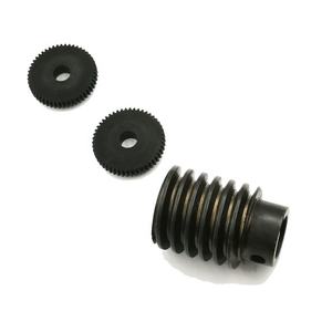
Reducing helical gears on a milling machine is a specific and methodical procedure that calls for a thorough understanding of gear geometry, device setup, and reducing methods. Helical equipments, characterized by their angled teeth, supply smoother and quieter procedure compared to stimulate equipments, making them essential in high-speed and high-load applications. This post outlines the step-by-step treatment to equipment helical gears utilizing an universal milling device, stressing essential estimations, tooling, and alignment methods.
(how to cut helical gears in the milling machine)
** Equipment and Tooling Demands **.
To cut helical gears, an universal milling equipment equipped with a separating head, tailstock, and a gear hob or type cutter is required. The dividing head has to can differential indexing to fit the helix angle. A single-form cutter or hob matching the gear’s component, stress angle, and helix angle is selected based on the equipment requirements. The milling machine’s table have to be rotated to line up with the helix angle, and a suitable gear train in between the dividing head and the table lead screw is required to synchronize rotational and straight movements.
** Computing Gear Parameters **.
The initial step involves establishing the gear’s critical parameters: module, number of teeth, helix angle, and pitch diameter. The helix angle (β) defines the tooth inclination and influences the configuration. The lead of the helix– the axial range for one full tooth change– is calculated using the formula:.
** Lead (L) = π × Pitch Diameter (D)/ tan( β) **.
This lead value determines the equipment train proportion between the separating head and the table feed screw. The equipment train ratio (GR) is acquired as:.
** GR = Lead of the Machine (L_m)/ Lead of the Gear (L) **.
Here, L_m is the inherent lead of the milling machine, commonly defined by the producer (e.g., 127 mm or 5 inches for royal equipments).
** Device Setup **.
1. ** Swivel the Table **: Rotate the milling maker table to match the helix angle (β). Guarantee the turning instructions corresponds to the gear’s hand (left or right).
2. ** Mount the Workpiece **: Secure the equipment blank between the separating head and tailstock using a mandrel. Straighten the blank’s axis parallel to the table.
3. ** Install the Cutter **: Make use of a helical equipment cutter representing the equipment’s module and stress angle. Setting the cutter centrally relative to the gear blank.
4. ** Establish the Gear Train **: Configure change equipments between the dividing head and the lead screw to accomplish the calculated equipment ratio. Engage the differential indexing system if needed for non-standard helix angles.
** Machining Refine **.
1. ** Indexing **: Utilize the splitting head to index the gear blank for each tooth room. The variety of divisions equals the gear’s tooth matter.
2. ** Depth of Cut **: Establish the initial cut depth based upon the equipment’s entire deepness (h = 2.25 × Module). Perform roughing and completing passes to attain the last tooth profile.
3. ** Cutting Movement **: Involve the automatic table feed to relocate the workpiece longitudinally while the cutter rotates. The integrated turning of the dividing head and table feed generates the helical course.
4. ** Lubrication **: Use cutting liquid to decrease warm, reduce device wear, and improve surface finish.
** Critical Factors to consider **.
– ** Differential Indexing **: For non-standard helix angles, the splitting head’s differential system makes up for mild mistakes in indexing by presenting a corrective turning during the reducing process.
– ** Tool Positioning **: Misalignment in between the cutter and workpiece lead to imprecise tooth profiles. Validate alignment utilizing a dial sign.
– ** Backlash Control **: Remove reaction in the equipment train and table feed mechanism to keep synchronization.
** Post-Machining Assessment **.
After cutting, inspect the equipment for dimensional accuracy making use of gear tooth calipers, an account projector, or a coordinate measuring device (CMM). Validate the helix angle with a sine bar or optical comparator. Examine surface coating and tooth get in touch with pattern using roll testing.
** Verdict **.
(how to cut helical gears in the milling machine)
Machining helical gears on a milling maker demands precise preparation, specific arrangement, and adherence to determined criteria. By integrating differential indexing, correct device choice, and integrated motion control, premium helical equipments can be created for applications calling for smooth torque transmission and decreased noise. Constant verification of placement, depth of cut, and lubrication ensures ideal outcomes, reinforcing the milling device’s flexibility in gear production.


