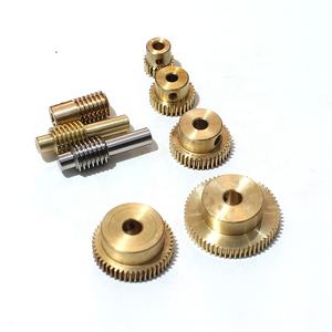
Calculating gear proportions is essential in mechanical engineering for designing power transmission systems. The equipment ratio specifies the relationship between input and outcome rotational speeds and torques. For easy makers with gears, the calculation relies on the number of teeth on fitting together gears or the diameters if teeth are not considered, though tooth count is liked for precision.
(how do you calculate the gear ratio with simple machines)
For 2 equipments in straight mesh, designate the input gear as the driving gear and the output equipment as the driven gear. The equipment proportion (GR) is the proportion of the driven gear’s teeth (N_driven) to the driving gear’s teeth (N_driving). Revealed mathematically: GR = N_driven/ N_driven. This proportion also equates to the input angular rate (ω_input) separated by the output angular speed (ω_output): GR = ω_input/ ω_output. An equipment ratio greater than one shows speed decrease and torque reproduction. A proportion less than one signifies speed rise and torque decrease.
In compound equipment trains with numerous stages, calculate the general gear ratio by increasing the individual ratios of each meshing pair. For instance, in a two-stage system, if the very first set has GR1 and the 2nd pair has GR2, the complete gear ratio GR_total = GR1 × GR2. Constantly reference each stage’s proportion to the input and result of that details phase. Intermediate equipments, known as idlers, influence rotational instructions yet not the size of the overall ratio because their tooth counts cancel out mathematically when proportions are multiplied.
Planetary equipment systems call for an unique strategy. These include a sunlight gear, world gears, and a ring equipment. The gear ratio depends on which component is repaired, which is input, and which is result. For example, with the ring equipment taken care of, input at the sun equipment, and outcome at the earth carrier, the ratio is GR = 1 + (N_ring/ N_sun), where N_ring and N_sun are the tooth counts of the ring and sunlight gears, specifically. This configuration provides high decrease ratios compactly.
Practical application calls for making sure equipments share the same component (metric) or diametral pitch (imperial) for appropriate meshing. Facility range should be properly determined based upon pitch sizes to prevent interference and ensure effective power transfer. Engineers should additionally account for performance losses from friction, commonly 1-2% per mesh for spur equipments, which a little decreases result torque compared to optimal calculations.
(how do you calculate the gear ratio with simple machines)
In recap, gear proportion calculation in simple equipments involves tooth matter ratios for direct meshes, item of ratios for substance trains, and specific formulas for planetary systems. This foundational knowledge makes it possible for mechanical engineers to create efficient transmissions for varied applications, stabilizing rate, torque, and spatial restrictions.


